
Dr. Ehsan Amini
The Highway Capacity Manual (HCM) provides comprehensive methodologies for analyzing highway facilities, from multilane to two-lane highways. These analyses are typically performed using Highway Capacity Software (HCS) to evaluate the segment at the macroscopic level. However, when engineers need to visualize traffic operations or perform detailed microsimulation analysis, they often require these facilities to be modeled and analyzed by a microsimulation software like TSIS-CORSIM.
The TrfFileConverter tool now includes a dedicated Highway Converter module that seamlessly bridges this gap, enabling HCS users to convert their HCS models directly into TSIS-CORSIM. This article provides an overview of the Highway Converter’s capabilities and how it facilitates the transition from capacity analysis to traffic simulation.
Understanding the Conversion Challenge
The transition from macroscopic simulation to a microscopic simulation represents a fundamental shift in how transportation facilities are evaluated. HCS operates at the macroscopic level, providing aggregate performance measures such as level of service, density, and speed based on analytical procedures defined in the HCM. TSIS-CORSIM, on the other hand, operates at the microscopic level, simulating individual vehicle movements and interactions. This requires a different file format (the TRF format), which represents the network as a series of connected links and nodes with detailed operational parameters. The challenge is converting HCS analytical results into TSIS-CORSIM’s network format, ensuring all critical parameters are preserved and the data structure matches what the simulation software expects.
The Highway Converter addresses this challenge by automatically extracting data from HCS files and generating properly formatted TRF files that can be directly imported into TSIS-CORSIM.
Principles and Definitions
The Highway Converter handles two distinct types of highway facilities, each with unique characteristics and conversion requirements. Multilane highways (Figure 1) are facilities with two or more lanes per direction, which may be undivided, divided, or feature a two-way left-turn lane (TWLTL). These facilities require bidirectional analysis, with separate consideration of forward and reverse direction operations. The converter must carefully manage the relationship between these two directions, ensuring that traffic flows are properly represented in both directions while maintaining network connectivity.

Figure 1. TRAFVU window for a multilane highway
Two-lane highways, on the other hand, are typically rural or suburban facilities with one lane in each direction, where passing opportunities and opposing traffic can significantly impact operations (Figure 2). These facilities often contain multiple segments, each with unique geometric characteristics such as horizontal curves and tangents. The converter must represent both the main segments and the subsegments within each segment, capturing the geometric and operational details that affect traffic behavior.

Figure 2. TRAFVU window for a two-lane highway
The conversion process extracts operational and geometric data from HCS files and translates them into the TRF record types required by TSIS-CORSIM. This translation ensures that all critical parameters (from free-flow speeds and grades to traffic volumes and truck percentages) are accurately preserved. The converter maintains the integrity of the original analysis while adapting it to the requirements of simulation software.
Multilane Highway Conversion
Multilane highway segments require careful handling of bidirectional operations. The converter extracts data for both forward and reverse directions, including:
- Segment names and identification
- Free-flow speeds that are automatically clamped to 90 mph maximum.
- Segment lengths and number of lanes
- Traffic volumes and truck percentages for multiple time periods
- Grade values that are clamped between -9% and +9% per TRF format requirements.
- Median type (Undivided, Divided, or TWLTL) to determine the appropriate template
The median type plays a crucial role in determining the appropriate template for conversion. Whether the facility is Undivided, Divided, or a TWLTL. Since modeling TWLTL is not applicable in TSIS-CORSIM for these types of medians on multilane highways, the converter will convert the file as a divided highway.
Node numbering follows a systematic approach, with forward direction nodes starting at 1 and reverse direction nodes starting at 1001, creating a clear separation that allows the simulation software to properly interpret the bidirectional nature of the facility.
Two-Lane Highway Facility Conversion
Two-lane highway facilities present additional complexity due to their multi-segment nature and geometric variations. Unlike multilane highways, which are typically analyzed as single segments, two-lane highways often consist of several segments, each with unique operational characteristics. The converter handles:
- Multiple Segments: Facilities can consist of several segments, each with unique operational characteristics.
- Subsegments: Each segment may contain multiple subsegments, including:
- Tangents (straight sections)
- Horizontal curves with specified radius, length, and superelevation
- Passing Conditions: Segments are classified as:
- Passing Constrained: No passing opportunities
- Passing Zone: Passing allowed
- Passing Lane: A passing lane for forward direction
- Opposing Traffic:
- Separate consideration of opposing direction volumes, which significantly
impact two-lane highway operations. - Free-flow speeds that are automatically clamped to a 70 mph maximum
- Grade values that are clamped between -9% and +9%
- Separate consideration of opposing direction volumes, which significantly
- Geometric Details: Curve control points are generated to accurately represent
horizontal alignment in the simulation.
Illustrative Example
Consider a two-lane highway facility modeled in HCS (Figure 3) with the following characteristics:
- Segment Type: Passing Constrained
- Total Length: 5,893 ft (1.12 miles)
- Free-Flow Speed: 60.0 mph
- Speed Limit: 50 mph
- Directional Demand: 1,000 veh/h
- Peak Hour Factor: 0.94
- Grade: 2% (for the forward direction)
- Lane Width: 12 ft
- Shoulder Width: 6 ft (paved)
- Heavy Vehicles: 5%

Figure 3. Segments page of HCS file
The facility consists of five subsegments (Figure 4) that define its horizontal alignment:
- Tangent: 679 ft
- Horizontal Curve: 1,939 ft (radius: 1,800 ft, superelevation: 0.0%)
- Tangent: 532 ft
- Horizontal Curve: 1,716 ft (radius: 1,400 ft, superelevation: 0.0%)
- Tangent: 1,027 ft

Figure 4. Details page of HCS file
The converter extracts this data from the HSC file and generates a TRF file with:
- Link name records (RT10) identifying each subsegment link
- Individual link geometry records (RT19) for each subsegment, connected with
sequential node numbering - Link operation records (RT20) containing:
- Passing code 1 (Passing Constrained) for all subsegments
- Free-flow speeds clamped to 70 mph maximum
- Grade values (5% in this example)
- Superelevation values (0% for both curves in this example, clamped
between 0% and 12%)
- Turn percentage records (RT25) for proper traffic distribution at nodes
- Curve control points (RT197 records) accurately representing the two
horizontal curves with their respective radii and superelevation - Entry link volume records (RT50) with the 1,000 veh/h demand properly
formatted - Node coordinates (RT195), ensuring the facility is represented as a
continuous network

Figure 5. Divide the long curves into three smaller curves, each with the same radius.
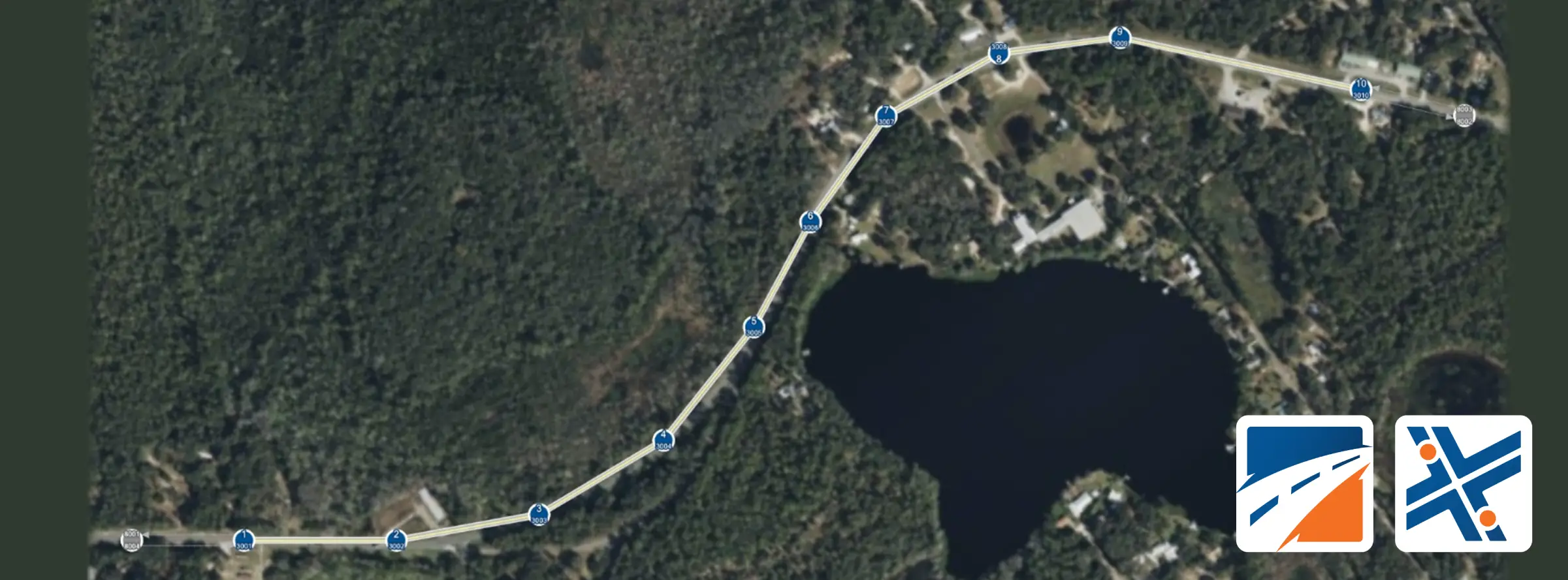
The resulting TRF file can be directly imported into TSIS-CORSIM for visualization and microsimulation analysis. If needed, you can add a background image in TSIS-CORSIM and run the software (Figure 6).

Figure 6. Converted two-lane highway in TSIS-CORSIM with background image.