
Dr. Shraddha Sagar
Freeway segmentation is essential for assessing both operational efficiency and safety, particularly when using Highway Safety Manual (HSM) methods. The complexity of segmentation increases based on ramp placements, especially with non-aligned ramps.
A fundamental rule in segmentation is that a new segment must always start at gore points, where the gore (the area separating the mainline and ramp) is 2 feet wide. This is the point where traffic behavior changes significantly, requiring a new segment to accurately represent operational dynamics.
Each segment is evaluated for homogeneity, ensuring that traffic volume, geometric design (e.g., lane width, shoulder width), and control features remain consistent. Homogeneous segments ensure that safety performance remains predictable across similar roadway sections. When any significant change in these characteristics occurs, a new segment begins to reflect the differing traffic behavior and safety risk.
All measurements in the segmentation process are taken relative to the reference line—the inside edge of the traveled roadway, typically serving the direction of increasing milepost numbers. This consistency ensures that all road features are measured against a single baseline, making it easier to identify changes that warrant new segments.
Segmentation becomes more intricate when dealing with asymmetrical ramps and speed change lanes. If the ramps are not aligned, special care must be taken to define segment boundaries that accurately capture the influence of both exit and entrance ramps on mainline traffic.
Why Homogeneous Segments?
Homogeneous segments are vital because they exhibit similar safety metrics. Changes in road characteristics (e.g., lane additions, merging zones) can lead to differing safety outcomes. By segmenting the freeway based on changes in traffic flow and design, analysts can ensure each segment is evaluated under the correct operational conditions, leading to more accurate safety
Example: I-75 and SR-6, Jasper, FL
Consider a 1-mile segment along I-75 that includes an asymmetrical diamond interchange at SR-6, as shown in Figure 1. The non-aligned ramp placements introduce complexities to the segmentation process. While the HSM does not provide explicit guidelines for segmenting such a facility, a practical approach can be taken using Highway Safety Software (HSS). In this example, it is assumed that the geometric conditions and traffic volumes remain consistent across the 1-mi segment.
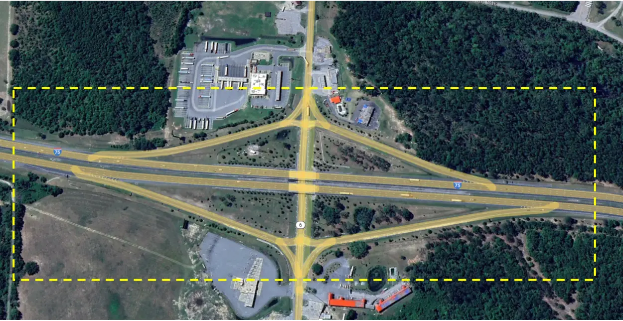
Figure 1. 1-mi study location on I-75
The first homogeneous segment begins at the project boundary and is divided at gore points, as shown in Figure 2, ensuring that speed change lanes are not split between segments. The exit ramps and entrance ramps are highlighted in orange and need to be analyzed separately using their respective Safety Performance Functions (SPFs). For analyzing this 1-mile segment, the freeway can potentially be divided into three mainline freeway segments and four speed-change lane segments to capture the distinct traffic behaviors and conditions.
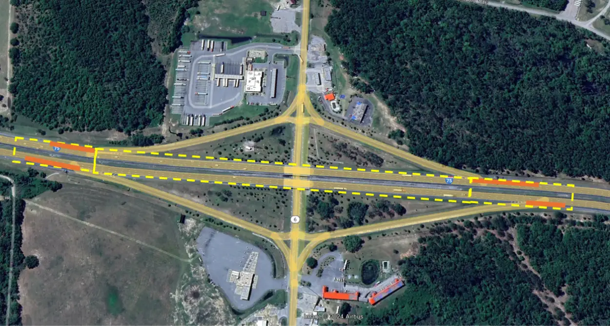
Figure 2. Initial segmentation configuration
Segment Length Calculation
Segment 1:
Segment 1 includes both an entrance and exit ramp, and to accurately estimate its effective length, the speed change lanes must be considered. The length of each speed change lane is measured from the gore point) to the taper point.
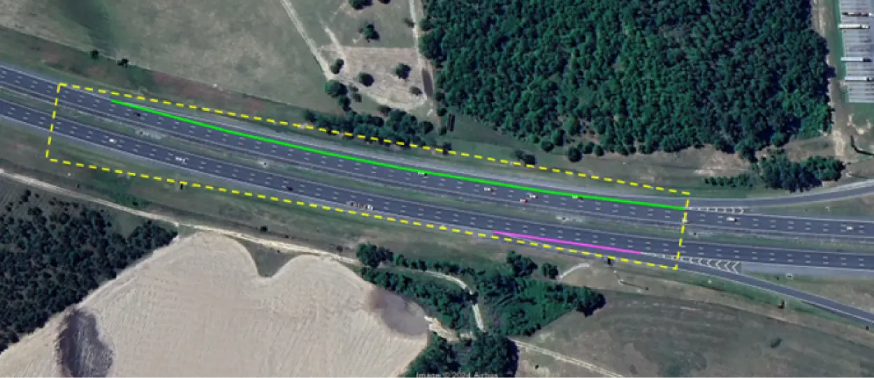
Figure 3. Segment 1, with two speed-change lanes
- Length of the segment 1, Lf1 = 1,610 ft
- Length of entrance ramp speed-change lane (marked as green) = 1,360 ft (0.258 mi)
- Length of exit ramp speed-change lane (marked as purple) = 335 ft (0.063 mi)
- Effective length of segment 1, L*1= 1610 – (1360/2) – (335/2) = 762.5 ft (0.144 mi)
Segment 2:
The second segment does not include any entrance or exit ramps, so the effective length of this segment is simply equal to the physical length of the segment itself. Since no speed change lanes are present, no adjustments are necessary for ramp influence.
Length of the segment 2, L2 = 2200 ft (0.417 mi)
Segment 3:
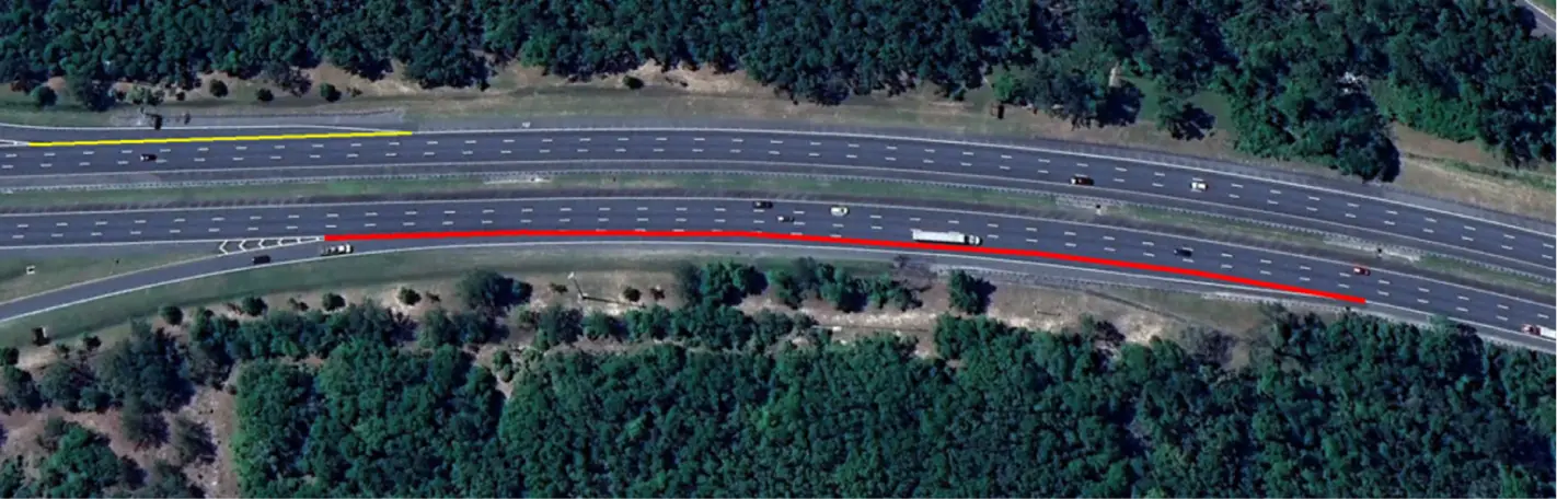
Figure 4. Segment 3, with two speed-change lanes
For the third segment, the same approach used for Segment 1 should be applied.
- Length of the segment 3, Lf3 = 1,470 ft
- Length of entrance ramp speed-change lane (marked as red) = 1,061ft (0.201 mi)
- Length of exit ramp speed-change lane (marked as yellow) = 339 ft (0.064 mi)
- Effective length of segment 3, L*3 = 1470 – (1061/2) – (339/2) = 770ft (0.146 mi)
These segments can be modeled in the Highway Safety Software (HSS) as part of a Freeway Facility, as shown in Figure 5:
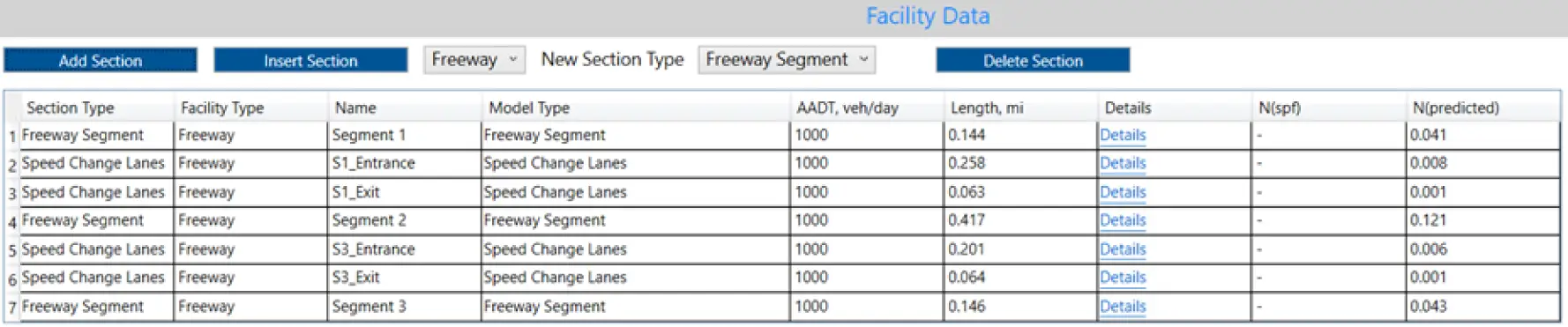
Figure 5. HSS Model